English page

シンプルなビープ音のほか、ユーザが設定した単音メロディ(最大61音)を鳴らすことができるモジュールです。
インターフェイスはGrove(I2C)とUSBに対応しています。
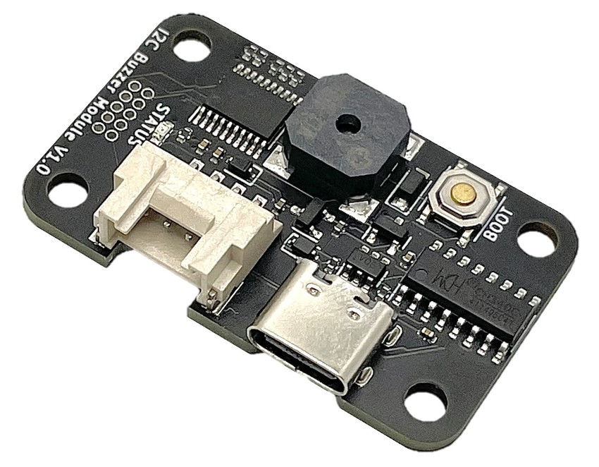
各部の名称

- 動作状態LED
- 点灯:モジュール動作中
- 1回点滅:正しいリモートコマンドを受け付けた
- 3回点滅:誤ったリモートコマンドを受け付けた
- 消灯:モジュール非動作中(モジュール電源OFF、モジュールの起動中など)
※点滅中もコマンドは受け付けています。
内容物
- 製品本体×1
販売
販売ページ(スイッチサイエンス)
※販売ページに表示されている在庫数のほかにも、追加の在庫を保有している場合がございます。大量注文や在庫に関する問い合わせはこちらまでご連絡ください。
通信仕様
Grove(I2C)
I2Cレジスタマップ.pdfUSBシリアル通信
通信コマンド仕様.pdf
仕様
- ブザー周波数:100Hz ~ 8kHz
- 通信インターフェース:USB、Grove互換コネクタ (I2C) 1
- USBシリアル通信
- ボーレート:9600 bps
- データビット:8 bit
- パリティ:なし
- ストップビット:1 bit
- I2C
- 最大通信速度:400 kbps
- 信号電圧:3.3 V(5Vトレラント)
- Grove電源電圧:3.0 V ~ 5.25 V
- USB電源電圧:4.75 V ~ 5.25V
- 最大消費電流:70 mA
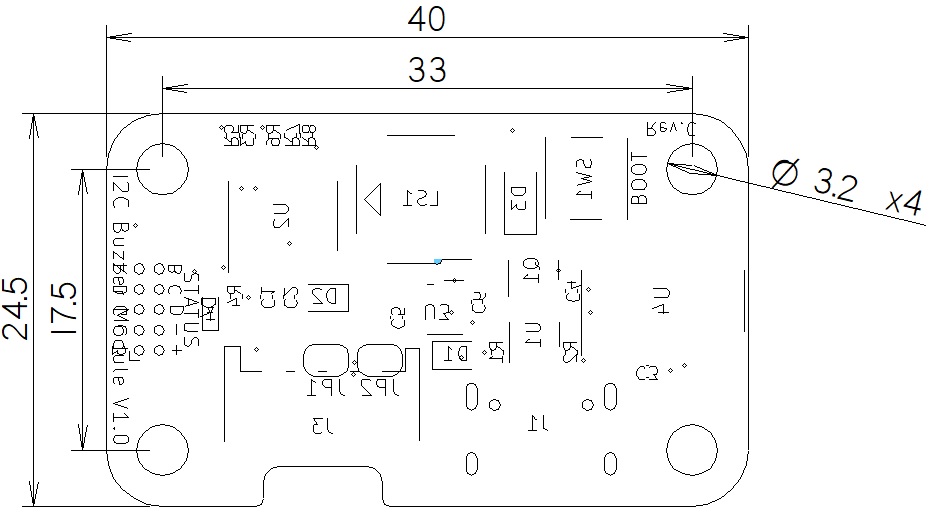
- 外形寸法:W40 x D24.5 x H7 mm
- その他
- USBシリアル変換IC:WCH CH340 2
ファームウェアのアップデート
詳細を見る
必要なもの
- 製品本体
- USB Type-Cケーブル
- PC
必要なソフトウェア
本製品に搭載しているSTMicroelectronics社のマイコンへの書込み用ソフト"STM32CubeProg"が必要です。下記のサイトからソフトウェアをダウンロードしインストールしてください。
https://www.st.com/ja/development-tools/stm32cubeprog.html
※本ソフトウェアをダウンロードするためにはmySTへの登録(無料)が必要です。
ファームウェアの書き換え手順
資料
回路図
- v1.0:schematic-v1_0.pdf
基板の外形寸法

DXFファイル:dimension_dxf.zip
3D CADデータ
STEPファイル:3d_step.zip
プログラム例
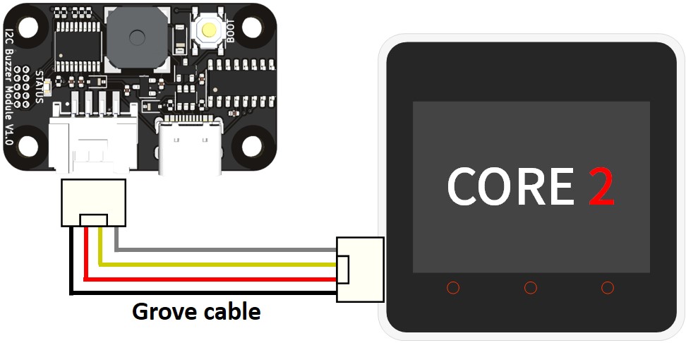
M5Stack Core2のGrove(I2C)を用いたプログラム例
配線図・サンプルコードを見る

#include <M5Core2.h>

#define BUZZER_I2C_DEV_ADDR	0x16
#define SBEEP_REG_ADDR			0x01
#define CBEEP_REG_ADDR			0x02
#define FREQ0_REG_ADDR			0x04

void setup() {
  M5.begin(true, true, true, true);

  union _16bit_u
  {
    uint16_t uint16_data;
    uint8_t uint8_data[2];
  };

  struct note_t
  {
    union _16bit_u frequency;
    union _16bit_u period;
  };

  M5.Lcd.clear();
  M5.Lcd.setCursor(0, 0);
  delay(500);


  // Simple Beep (1kHz, 50ms, x3)
  M5.Lcd.setFont(FSB24);
  M5.Lcd.println();
  M5.Lcd.println("Simple Beep");
  M5.Lcd.setFont(FSB18);
  M5.Lcd.println("1kHz, 50ms, x3");
  delay(500);
  Wire.beginTransmission(BUZZER_I2C_DEV_ADDR);
  Wire.write(SBEEP_REG_ADDR);
  Wire.write(0b10000111); // 1kHz, 50ms, x3
  Wire.endTransmission();
  delay(2000);


  // Custom Beep (Amaryllis)
  M5.Lcd.clear();
  M5.Lcd.setCursor(0, 0);
  M5.Lcd.setFont(FSB24);
  M5.Lcd.println();
  M5.Lcd.println("Custom Beep");
  M5.Lcd.setFont(FSB18);
  M5.Lcd.println("Amaryllis");
  const uint16_t freqs[] = {784,880,784,1047,784,880,784,880,880,784,880,784,698,659,587,659,523,784,880,784,1047,784,880,784,880,880,784,880,784,698,659,587,523,65535};
  const uint16_t periods[] = {300,300,300,300,300,300,600,300,300,300,300,150,150,150,150,300,300,300,300,300,300,300,300,600,300,300,300,300,150,150,150,150,600,0};
  const int note_num = sizeof(freqs) / sizeof(uint16_t);
  struct note_t notes[note_num];
  for(int i = 0; i < note_num; i++) {
    notes[i].frequency.uint16_data = freqs[i];
    notes[i].period.uint16_data = periods[i];
  }

#define NOTE_BLOCK_SIZE 16  // Write in separate blocks because it cannot write at once.
  int repeat_cnt = note_num / NOTE_BLOCK_SIZE + 1;
  for(int repeat_i = 0; repeat_i < repeat_cnt; repeat_i++) {
    Wire.beginTransmission(BUZZER_I2C_DEV_ADDR);
    Wire.write(FREQ0_REG_ADDR + repeat_i * NOTE_BLOCK_SIZE * 4);
    int buf_i = (note_num > (repeat_i + 1) * NOTE_BLOCK_SIZE) ? (repeat_i + 1) * NOTE_BLOCK_SIZE : note_num;
    int start_num = repeat_i * NOTE_BLOCK_SIZE;
    int end_num = (note_num > (start_num + NOTE_BLOCK_SIZE)) ? start_num + NOTE_BLOCK_SIZE : note_num;
    for(int note_i = start_num; note_i < end_num; note_i++) {
      Wire.write(notes[note_i].frequency.uint8_data[0]);
      Wire.write(notes[note_i].frequency.uint8_data[1]);
      Wire.write(notes[note_i].period.uint8_data[0]);
      Wire.write(notes[note_i].period.uint8_data[1]);
    }
    Wire.endTransmission();
    delay(500); // wait for device ready
  }

  Wire.beginTransmission(BUZZER_I2C_DEV_ADDR);
  Wire.write(CBEEP_REG_ADDR);
  Wire.write(1);  // repeat: x1
  Wire.endTransmission();
}

void loop() {
}