Japanese page
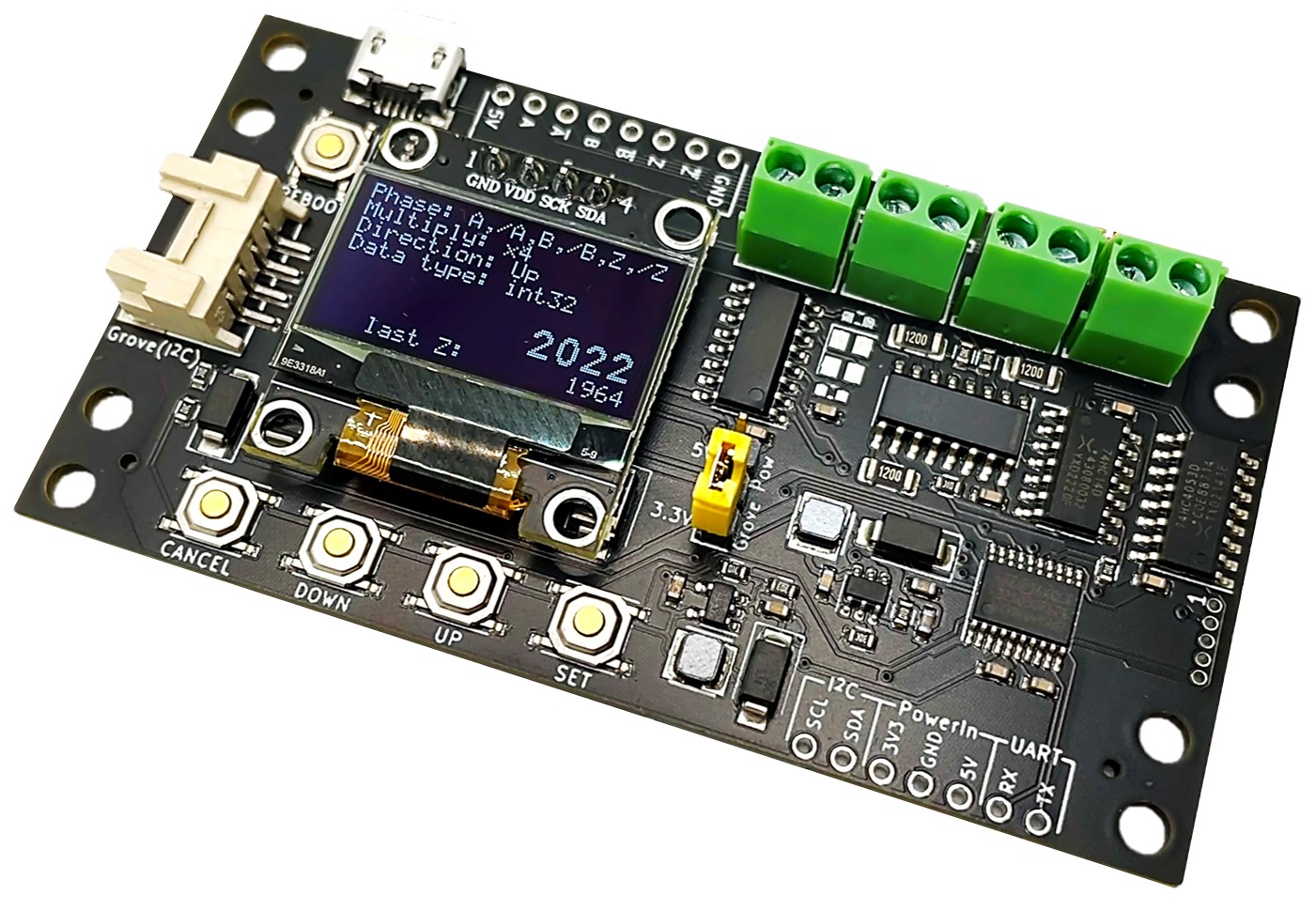
This module counts incremental encoder pulses and outputs the count.
2-phase (A, B) and 3-phase (A, B, Z) encoders are supported, including open-collector, voltage-output, and line-driver types.
USB and Grove (I2C) are supported as communication interfaces.
Power options include USB bus power, Grove (3.3V or 5V), and external input (5V or 3.3V).
Supports DIN-rail and screw mounting.
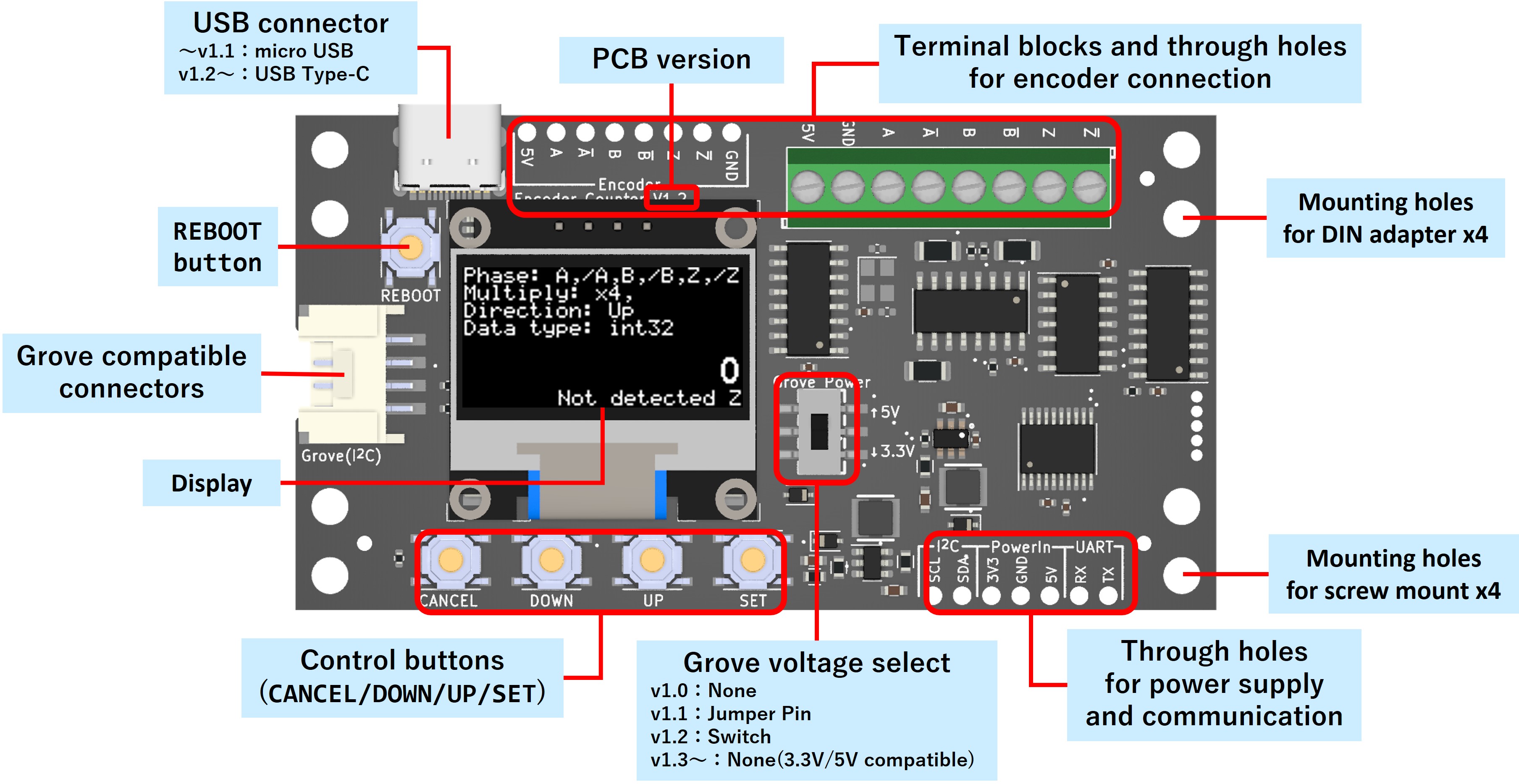
Part Names
Sales
Please contact us for bulk orders and inventory inquiries.
Included Items
Board ×1
* Encoders, various cables, and mounting adapters are not included.
How to use
Connect an encoder
- Line driver output (DC5V)
- 3 phase
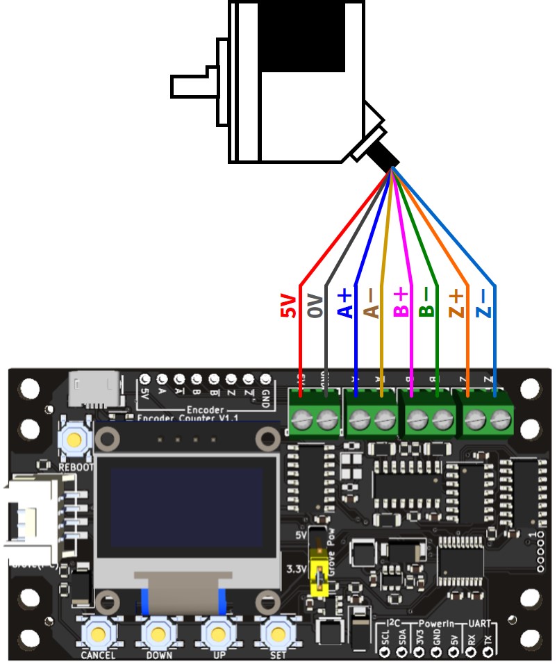
- 2 phase
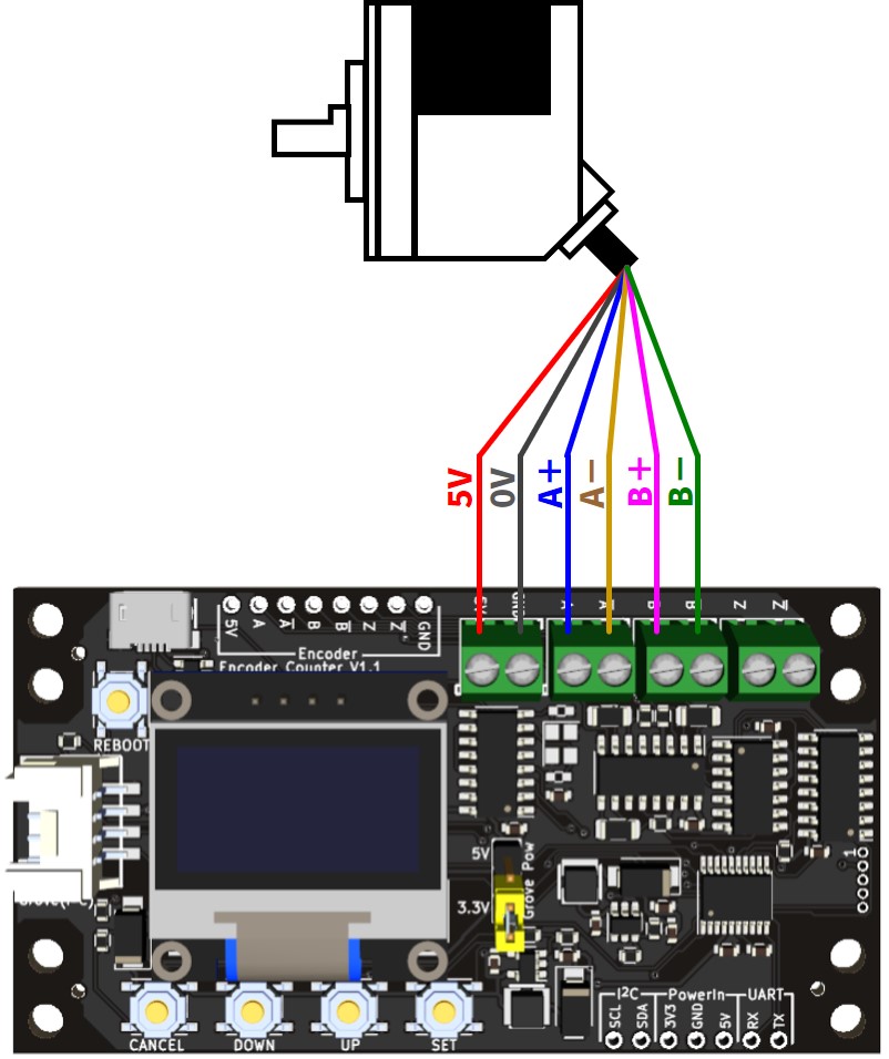
- 3 phase
- Voltage output / NPN open collector output (DC5V) 1
- 3 phase
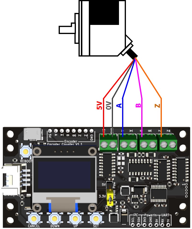
- 2 phase
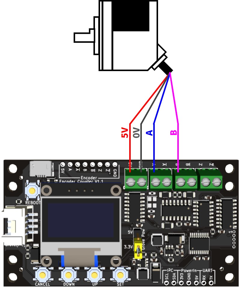
- 3 phase
- Mechanical encoder
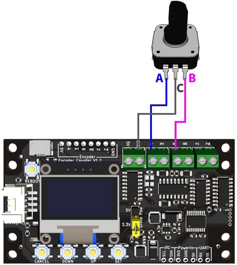
* Since the terminal blocks and the through holes for connecting a encoder are electrically connected in the board, the encoder can be connected to the through holes instead of the terminal blocks.
- Line driver output (DC5V)
Connect to power source
Please supply power in one of the following ways.- USB power supply (5V)
- Grove compatible connector (3.3V/5V)
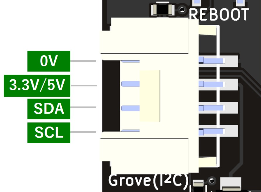
Pinout - Through hole for power supply (5V)
- Through hole for power supply (3.3V)
* Do not connect multiple power supplies to the same voltage system because the USB and power supply through-holes (5V) for the 5V system and the Grove connector and power supply through-hole (3.3V) for the 3.3V system are electrically connected in the board.
* It is acceptable to connect the power supply to both the 5V and 3.3V systems. For example, you may supply power from both USB (5V) and Grove (3.3V).
* Connect a power supply that can cover the encoder’s power consumption.Configure
Set up the encoder and communication using the buttons on the board or I2C commands.
Communication Specifications
I2C
Register MapSerial communication (USB, UART)
- Output format
- When Z-phase is enabled:
<Count Value>:<Count value at last detection of Z phase>:<After Z-phase detection: 1, Before Z-phase detection: 0>\n(e.g.12345:7890:1\n) - When Z-phase is disabled:
<Count Value>\n(e.g.12345\n)
- When Z-phase is enabled:
- Command
Send the following single character (without line feed code) to execute.c: Get count value. Sends a string in the output format above; disabled if USB Tx Mode is enabled.r: Reset count. Sets the count value to the initial value and Z-phase to the undetected state.
- Output format
Specifications
- Supported encoders
- Phase: 2-phase (A, B) , 3-phase (A, B, Z)
- Output signal type: 5V line driver output(AM26C31 equivalent), 5V voltage output, Open collector output
- Power supply voltage: 5V (* when power is supplied from this product)
- Maximum current consumption of encoder: Less than 250 mA (* when power is supplied from this product)
- Counter
- Number of input channels: 1
- Maximum input frequency: 5 MHz (* depends on output method and wiring environment)
- Counter update period: 1 ms
- Count range: 32 bit (signed/unsigned selectable)
- Communication Interface
- USB
- Grove compatible connector (I2C)
- Through hole (UART/I2C)
- Power supply method
- USB bus power
- Grove compatible connector (3.3V/5V)
- Through hole (3.3V/5V)
- Serial communication (USB, UART)
- Baud rate: 921600 bps
- Data bits: 8 bit
- Parity: None
- Stop bits: 1 bit
- UART signal voltage: 3.3 V
- I2C
- Maximum communication clock: 400 kbps
- Signal voltage: 3.3V
- Dimension W80 x D43 x H12 mm
- Miscellaneous
- USB Serial Communication IC: WCH CH340 2
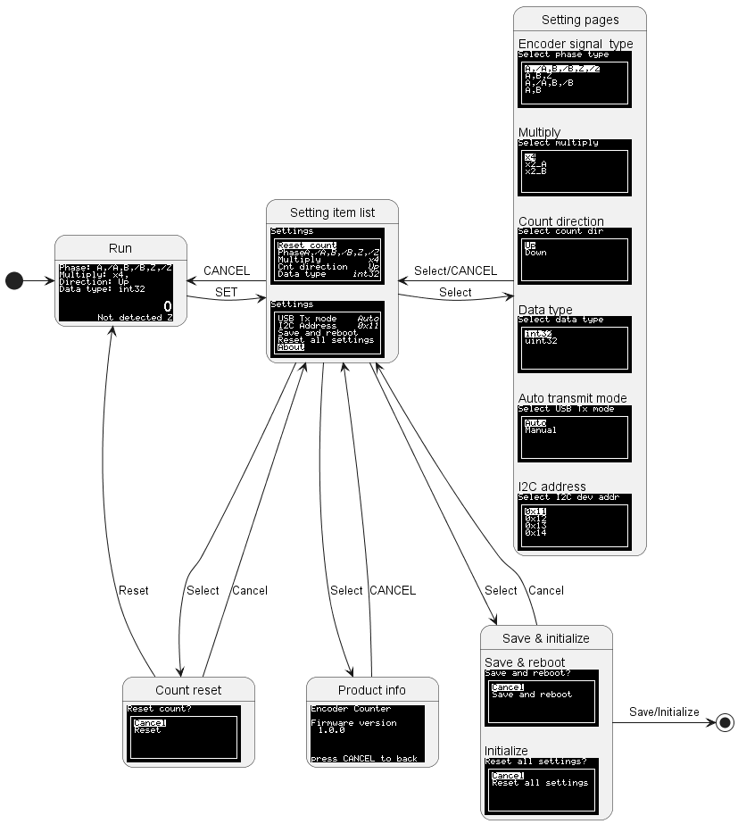
Screen Transition Diagram
Description of Setting Items
Reset countCount reset. Initializes the count value and sets the Z-phase to the undetected state.PhasePhase and output method settings- *
A,/A,B,/B,Z,/ZOutput phase: 3-phase, Output method: line driver output A,B,ZOutput phase: 3-phase, Output method: voltage output/open collector outputA,/A,B,/BOutput phase: 2-phase, Output method: line driver outputA,BOutput phase: 2-phase, Output method: voltage output/open collector output
- *
MultiplyMultiplier setting- *
x44 times x2_A2 times(Counting at A-phase edge)x2_B2 times(Counting at B-phase edge)
- *
Cnt directionCount direction- *
Up Down
- *
Data typeData type of count value- *
int32Signed 32-bit integer (-2147483648 ~ 2147483647, Initial value: 0) uint32Unsigned 32-bit integer (0 ~ 4294967295, Initial value: 2147483648)
- *
USB Tx ModeSetting the method of acquiring count values via USB and UART- *
AutoAutomatic mode. Count values are automatically sent in 1 ms cycles. ManualManual mode. The count value is sent when the command (c) is entered.
- *
I2C AddressI2C device address- *
0x11 0x120x130x14
- *
Save and rebootSave the changed parameters and rebootReset all settingsRestore all items to factory settings and rebootAboutShow product information and firmware version
* Factory default setting
How to Mount
DIN Rail Mount
Screw the DIN rail adapter (Phoenix Contact 1201578) as shown in the image.
* DIN rail adapter, screws, etc. are not included.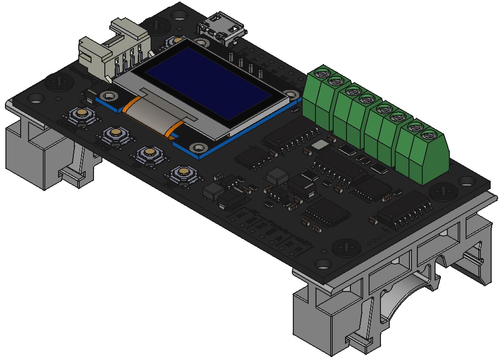
Screw Mount
Fix it to the desired board using spacers, etc.
* Spacers, screws, etc. are not included.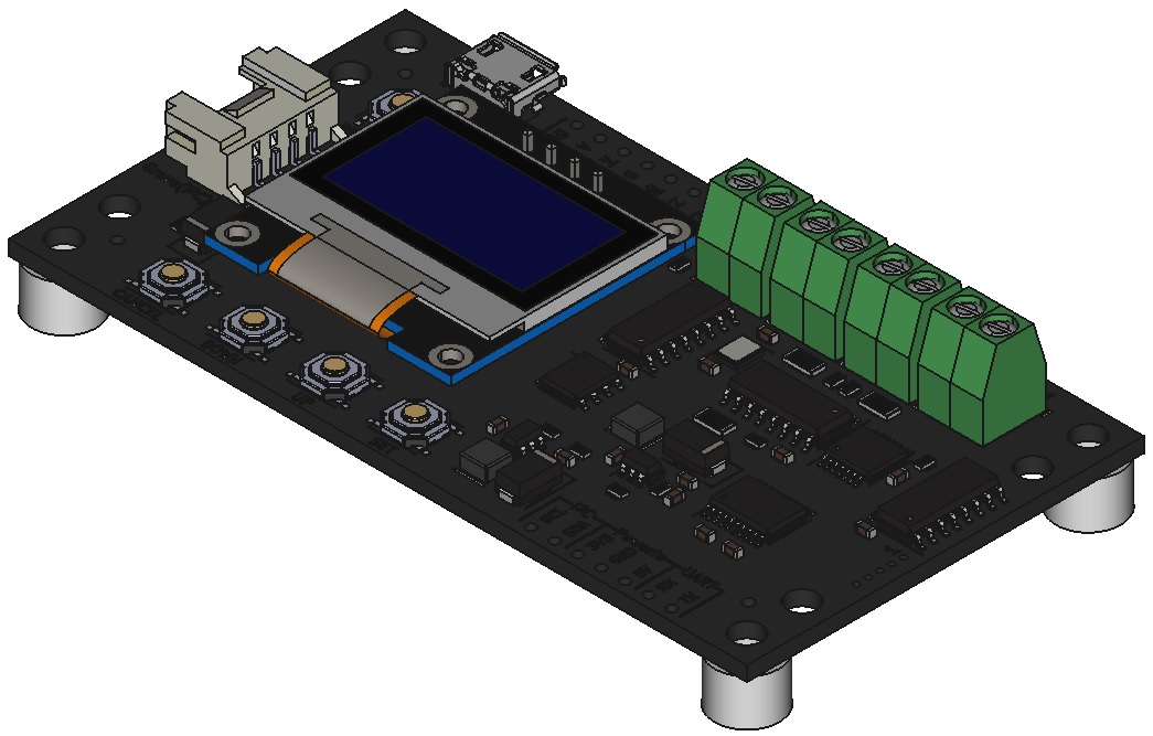
Update Firmware
See details
What You Need
- Encoder Counter
- USB cable
- PC
Required Software
“STM32CubeProg” that software for writing to the STMicroelectronics microcontroller installed in this product is required. Please download and install the software from the following website.
https://www.st.com/en/development-tools/stm32cubeprog.html
* Registration to myST (free of charge) is required to download this software.
Procedure
- Download the latest version of the firmware from here.
- If an encoder, Grove cable, etc. are connected to the product, disconnect all of them.
- Shifts to boot loader mode. While holding down the
CANCELbutton, plug the USB cable into the product and apply power. If nothing appears on the display, you have succeeded. If any text or other information appears on the display, please operate again. - Write firmware from the STM32CubeProg. Follow the instructions on this page to write the firmware.
- Press the
REBOOTbutton.
Documents
Schematics
- v1.0: schematic-v1_0.pdf
- v1.1: schematic-v1_1.pdf
- v1.2: schematic-v1_2.pdf
- v1.3: schematic-v1_3.pdf
Dimensions
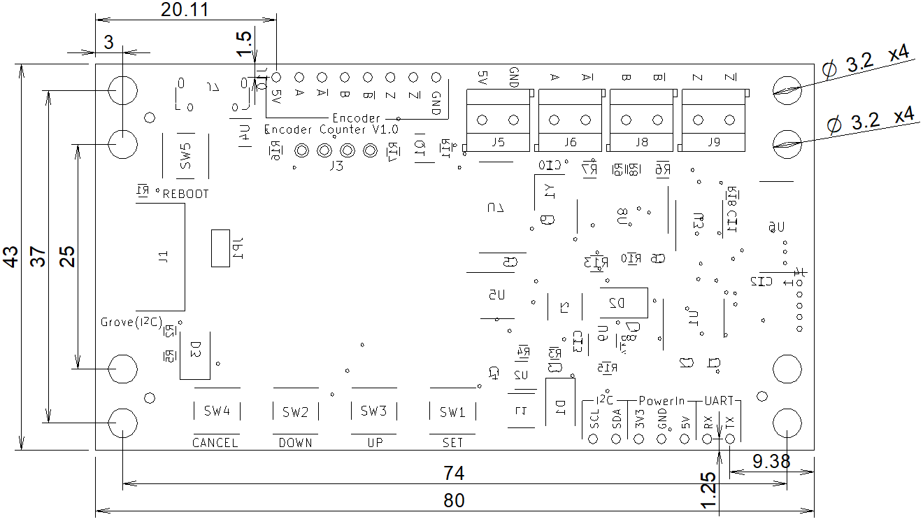 DXF file: dimensional_dxf.zip
3D CAD Data
STEP file: encoder_counter_step.zip
Sample Code
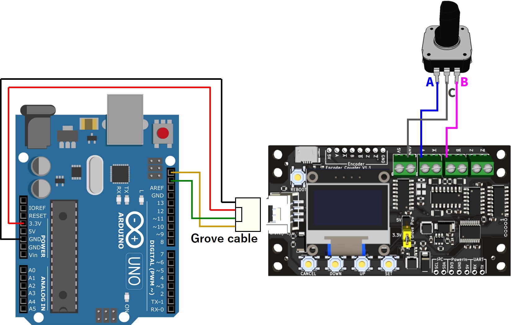
Acquiring Count Value using I2C on Arduino
See wiring diagram and sample code
#include <stdint.h>
#include <Wire.h>

#define I2C_SLAVE_DEV_ADDR    0x11

// Register address
#define ESTATUS_REG_ADDR    0x01
#define CRST_REG_ADDR       0x02
#define CVAL_REG_ADDR       0x03  // 0x03 - 0x06
#define RCVAL_REG_ADDR      0x07  // 0x07 - 0x0A
#define ECONF_REG_ADDR      0x0B
#define CCONF_REG_ADDR      0x0C
#define VMAJOR_REG_ADDR     0x0D
#define VMINOR_REG_ADDR     0x0E
#define VPATCH_REG_ADDR     0x0F
#define SYSRBT_REG_ADDR     0x10
#define I2CADDR_REG_ADDR    0x11
#define INIT_REG_ADDR       0x12

typedef union _32bit_u
{
  uint8_t uint8_data[4];
  uint32_t uint32_data;
  int32_t int32_data;
} _32bit_u;

void setup() {
  // Communication function init
  Serial.begin(115200);
  while (!Serial);

  // I2C init
  Wire.begin();
  Wire.setClock(400000);

  byte error;
  // Set encoder config
  // ECONF: Data type=int32, Count dir=Up, Multiply=x2_A, Phase=A,B
  uint8_t econf = 0x07;
  Wire.beginTransmission(I2C_SLAVE_DEV_ADDR);
  Wire.write(ECONF_REG_ADDR);
  Wire.write(econf);
  error = Wire.endTransmission();
  if (error){
    Serial.print("error=");Serial.println(error);
  }
  delay(4000);  // Wait until the config is written and the device reboots
}

void loop() {
  delay(100);

  // Read encoder count
  _32bit_u count;
  Wire.beginTransmission(I2C_SLAVE_DEV_ADDR);
  Wire.write(CVAL_REG_ADDR);
  Wire.endTransmission(false);
  Wire.requestFrom(I2C_SLAVE_DEV_ADDR, 4);
  for(int i = 0; i < 4; i++) {
    count.uint8_data[i] = Wire.read();
  }
  Serial.print("count = ");Serial.println(count.int32_data);
}
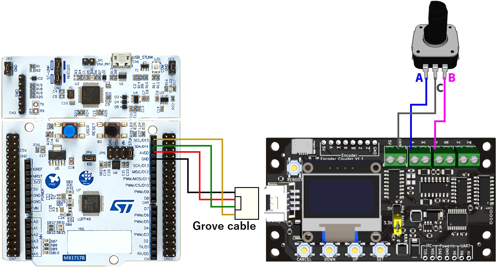
Acquiring Count Value using I2C on STM32 (Nucleo)
See wiring diagram and sample code
Sample code (only the main part is extracted)
#include <stdio.h>
#include <stdbool.h>
#include <stdint.h>
#include "i2c.h"
#include "usart.h"

typedef union _32bit_u
{
	uint32_t uint32_data;
	int32_t int32_data;
	uint8_t uint8_data[4];
} _32bit_u;

#define I2C_MASTER_INSTANCE		I2C1
#define I2C_MASTER_HANDLE_PTR	&hi2c1

#define I2C_SLAVE_DEV_ADDR		0x11

// Register address
#define ESTATUS_REG_ADDR		0x01
#define CRST_REG_ADDR			  0x02
#define CVAL_REG_ADDR			  0x03	// 0x03 - 0x06
#define RCVAL_REG_ADDR			0x07	// 0x07 - 0x0A
#define ECONF_REG_ADDR			0x0B
#define CCONF_REG_ADDR			0x0C
#define VMAJOR_REG_ADDR			0x0D
#define VMINOR_REG_ADDR			0x0E
#define VPATCH_REG_ADDR			0x0F
#define SYSRBT_REG_ADDR			0x10
#define I2CADDR_REG_ADDR		0x11
#define INIT_REG_ADDR			  0x12

int main(void)
{
  // ----- Omit initialization process ----- //

  HAL_StatusTypeDef status;

  // Set encoder config
  // ECONF: Data type=int32, Count dir=Up, Multiply=x2_A, Phase=A,B
  uint8_t econf = 0x07;
	status = HAL_I2C_Mem_Write(I2C_MASTER_HANDLE_PTR, I2C_SLAVE_DEV_ADDR << 1, ECONF_REG_ADDR, I2C_MEMADD_SIZE_8BIT, &econf, 1, 1000);
	if(status != HAL_OK)
		printf("Error: %d\n", status);
	HAL_Delay(4000);  // Wait until the config is written and the device reboots

  while (1) {
    HAL_Delay(100);

    // Read encoder count
    _32bit_u count;
    status = HAL_I2C_Mem_Read(I2C_MASTER_HANDLE_PTR, I2C_SLAVE_DEV_ADDR << 1, CVAL_REG_ADDR, I2C_MEMADD_SIZE_8BIT, &count.uint8_data[0], 4, 1000);
    if(status == HAL_OK)
      printf("count = %d\n", count.int32_data);
    else
      printf("Error: %d\n", status);
  }
}
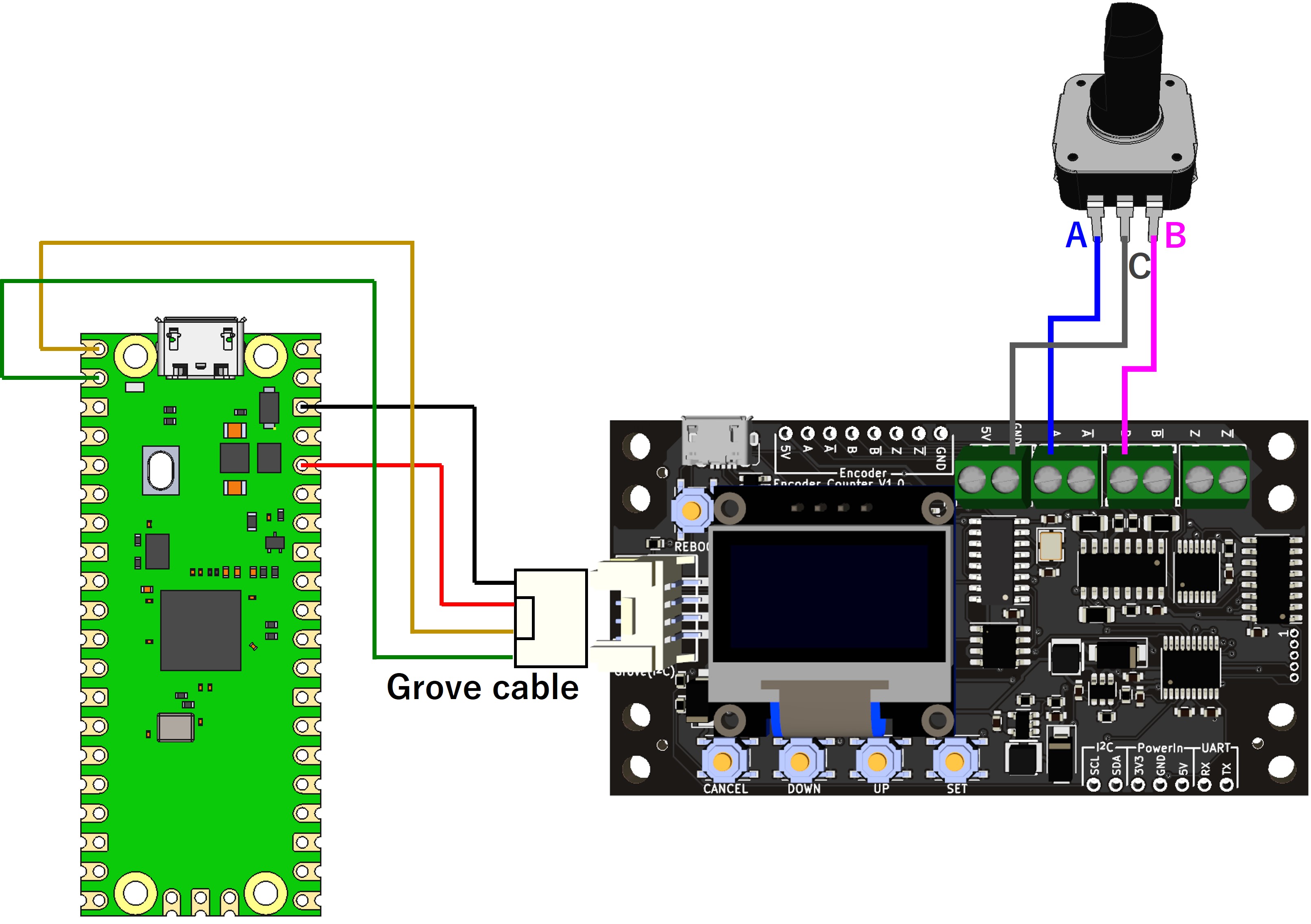
Acquiring Count Value using I2C on Raspberry Pi Pico (MicroPython)
See wiring diagram and sample code
from machine import Pin, I2C
import utime
import struct

I2C_SLAVE_DEV_ADDR = 0x11
ECONF_REG_ADDR = 0x0B
CVAL_REG_ADDR = 0x03

# I2C init (SDA:0pin, SCL:1pin)
i2c = I2C(0, scl=Pin(1), sda=Pin(0), freq=100000)

# Write 0x07 to ECONF(0x0B)
i2c.writeto_mem(I2C_SLAVE_DEV_ADDR, ECONF_REG_ADDR, b'\x07')

# Wait until the config is written and the device reboots
print("Rebooting...")
utime.sleep(4)

while True:
    utime.sleep(0.1)
    # Read 4 bytes from CVAL(0x03)
    data = i2c.readfrom_mem(I2C_SLAVE_DEV_ADDR, CVAL_REG_ADDR, 4)

    # Little-endian conversion to type int32
    value = struct.unpack('<i', data)[0]  # '<' means little-endian

    # Output result
    print("val:", value)
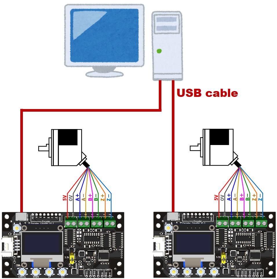
Acquiring Count Value of 2 encoders via USB connection
See wiring diagram and sample code
Sample code (.NET 6.0)
using System;
using System.IO.Ports;  // https://www.nuget.org/packages/System.IO.Ports
using System.Collections.Concurrent;

public class Counter
{
    public bool z_enable;
    public int count, last_z_count;
    public bool z_detected;

    public Counter()
    {
        z_enable = false;
        count = 0;
        last_z_count = 0;
        z_detected = false;
    }

    public void convertValue(string s)
    {
        string[] words = s.Split(':');
        switch (words.Length)
        {
            case 1:
                z_enable = false;
                try
                {
                    count = Int32.Parse(words[0]);
                }
                catch (FormatException)
                {
                    Console.WriteLine($"Unable to parse '{s}'");
                }
                break;
            case 3:
                z_enable = true;
                try
                {
                    count = Int32.Parse(words[0]);
                    last_z_count = Int32.Parse(words[1]);
                    z_detected = Int32.Parse(words[2]) == 1 ? true : false;
                }
                catch (FormatException)
                {
                    Console.WriteLine($"Unable to parse '{s}'");
                }
                break;
            default:
                Console.WriteLine($"Unable to parse '{s}'");
                break;
        }
    }
}

public class Obtain2EncoderCounterValue
{
    static bool _continue;
    static SerialPort? _serialPort1, _serialPort2;
    static ConcurrentQueue<Counter> _queue1 = new ConcurrentQueue<Counter>(), _queue2 = new ConcurrentQueue<Counter>();

    public static void Main()
    {
        string message;
        StringComparer stringComparer = StringComparer.OrdinalIgnoreCase;
        Thread readThread1 = new Thread(Read1);
        Thread readThread2 = new Thread(Read2);
        Thread mergeThread = new Thread(Merge);

        Console.WriteLine("Output synchronized values of 2 encoder counters\n");

        printAvailablePorts();
        Console.Write("First  encoder counter: ");
        _serialPort1 = new SerialPort(InputPortName(), 921600, Parity.None, 8, StopBits.One);
        Console.Write("Second encoder counter: ");
        _serialPort2 = new SerialPort(InputPortName(), 921600, Parity.None, 8, StopBits.One);

        _serialPort1.ReadTimeout = 500;
        _serialPort1.WriteTimeout = 500;
        _serialPort2.ReadTimeout = 500;
        _serialPort2.WriteTimeout = 500;

        Console.WriteLine("{0}\t{1}", _serialPort1.IsOpen, _serialPort2.IsOpen);
        _serialPort1.Open();
        _serialPort2.Open();
        _continue = true;
        readThread1.Start();
        readThread2.Start();
        mergeThread.Start();

        Console.WriteLine("Type QUIT to exit");

        while (_continue)
        {
            message = Console.ReadLine()!;

            if (stringComparer.Equals("quit", message))
            {
                _continue = false;
            }
        }

        readThread1.Join();
        readThread2.Join();
        mergeThread.Join();
        _serialPort1.Close();
        _serialPort2.Close();
    }

    public static void Read1()
    {
        while (_continue)
        {
            try
            {
                Counter c = new Counter();
                string message = _serialPort1!.ReadLine();
                c.convertValue(message);
                _queue1.Enqueue(c);
            }
            catch (TimeoutException) { }
        }
    }

    public static void Read2()
    {
        while (_continue)
        {
            try
            {
                Counter c = new Counter();
                string message = _serialPort2!.ReadLine();
                c.convertValue(message);
                _queue2.Enqueue(c);
            }
            catch (TimeoutException) { }
        }
    }

    public static void Merge()
    {
        int i = 0;
        while (_continue)
        {
            if(_queue1.Count() > 0 && _queue2.Count() > 0)
            {
                Counter c1, c2;
                if(_queue1.TryDequeue(out Counter? a))
                {
                    c1 = a!;
                } else
                {
                    continue;
                }

                if(_queue2.TryDequeue(out Counter? b))
                {
                    c2 = b!;
                } else
                {
                    continue;
                }
                string text;
                if(c1.z_enable && c2.z_enable)
                    text = $"{i++}\tc1:{c1.count},{c1.last_z_count},{c1.z_detected}\tc2:{c2.count},{c2.last_z_count},{c2.z_detected}";
                else if(c1.z_enable && !c2.z_enable)
                    text = $"{i++}\tc1:{c1.count},{c1.last_z_count},{c1.z_detected}\tc2:{c2.count}";
                else if(!c1.z_enable && c2.z_enable)
                    text = $"{i++}\tc1:{c1.count}\tc2:{c2.count},{c2.last_z_count},{c2.z_detected}";
                else
                    text = $"{i++}\tc1:{c1.count}\tc2:{c2.count}";
                Console.WriteLine(text);
                File.AppendAllText(@"./output.txt", text.Replace(",", "\t").Replace("c1:", "").Replace("c2:", "") + '\n');
            }
        }
    }

    public static void printAvailablePorts()
    {
        Console.WriteLine("Available Ports:");
        foreach (string s in SerialPort.GetPortNames())
        {
            Console.WriteLine("\t{0}", s);
        }
    }

    public static string InputPortName()
    {
        string portName;

        string[] ports = SerialPort.GetPortNames();
        string defaultPortName = ports.Length >= 2 ? ports[^2] : "COM1";
        Console.Write("Enter COM port value (Default: {0}): ", defaultPortName);
        portName = Console.ReadLine()!;

        if (portName == "" || !(portName.ToLower()).StartsWith("com"))
        {
            portName = defaultPortName;
        }
        return portName;
    }
}
Download
- Source code
- Executable file: Release.zip
The A, B, and Z pins are weakly pulled up to the 5V pin with a 10kΩ internal pull-up resistor. For open collector outputs, increase the pull-up by adding an external pull-up resistor if necessary. ↩︎
Basically, the USB driver is automatically installed when connected to a PC via USB, but if the USB driver is not automatically installed, please install CH341SER.EXE at the bottom of the page here. ↩︎

