Japanese page
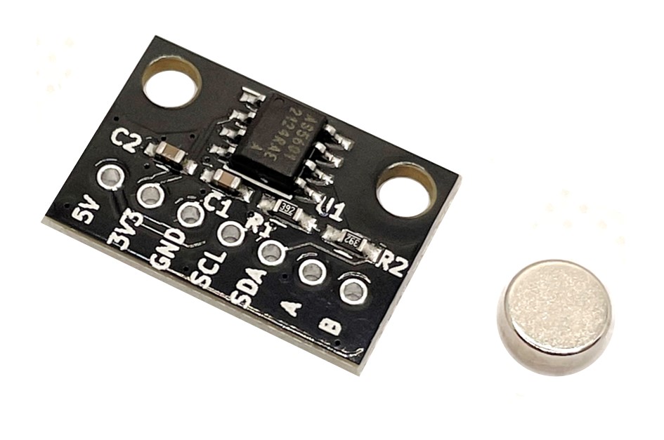
Breakout board for the AS5601 (ams AG) magnetic absolute rotary encoder with 12-bit (4096 ppr) resolution and 2.54 mm pitch.
A neodymium magnet is included.
Provides 5V/3.3V/GND power pins and I2C and A/B phase incremental output pins. The supply voltage is 5V or 3.3V.
Features
- High resolution: 4096ppr (incremental output is up to 2048ppr)
- Magnetic type enables non-contact angle measurement, excellent reliability and durability
- Interface
- I2C: Angle reading and operation setting are possible by accessing the config register
- Incremental output: Quadrature output of A/B phase with configurable resolution from 8ppr to 2048ppr
- Sampling time: 150 us
- Can read values even if the AS5601 and magnet centers are offset by about 1 mm
Sales
Please contact us for bulk orders and inventory inquiries.
Included Items
- Board ×1
- Neodymium magnet ×1
Specifications
- Board size: W20 x D13.5 mm
- Mounting holes: 15mm pitch, M3 x 2
- Magnet size: Φ6 x 2.5 mm
- Magnetization: Diametric
- When supplying 5V for power supply voltage, leave the 3.3V pin open. When supplying 3.3V, also supply 3.3V to the 5V pin.
- PUSH pin is not connected
How to mount
- Attach the included magnet to the center of the rotor shaft.
- Attach the board to the fixture so that the center of the AS5601 aligns with the center of the magnet.
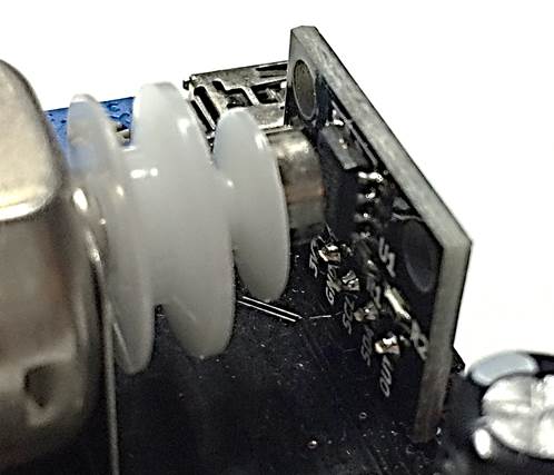
Example program with Arduino
Angle acquisition via I2C
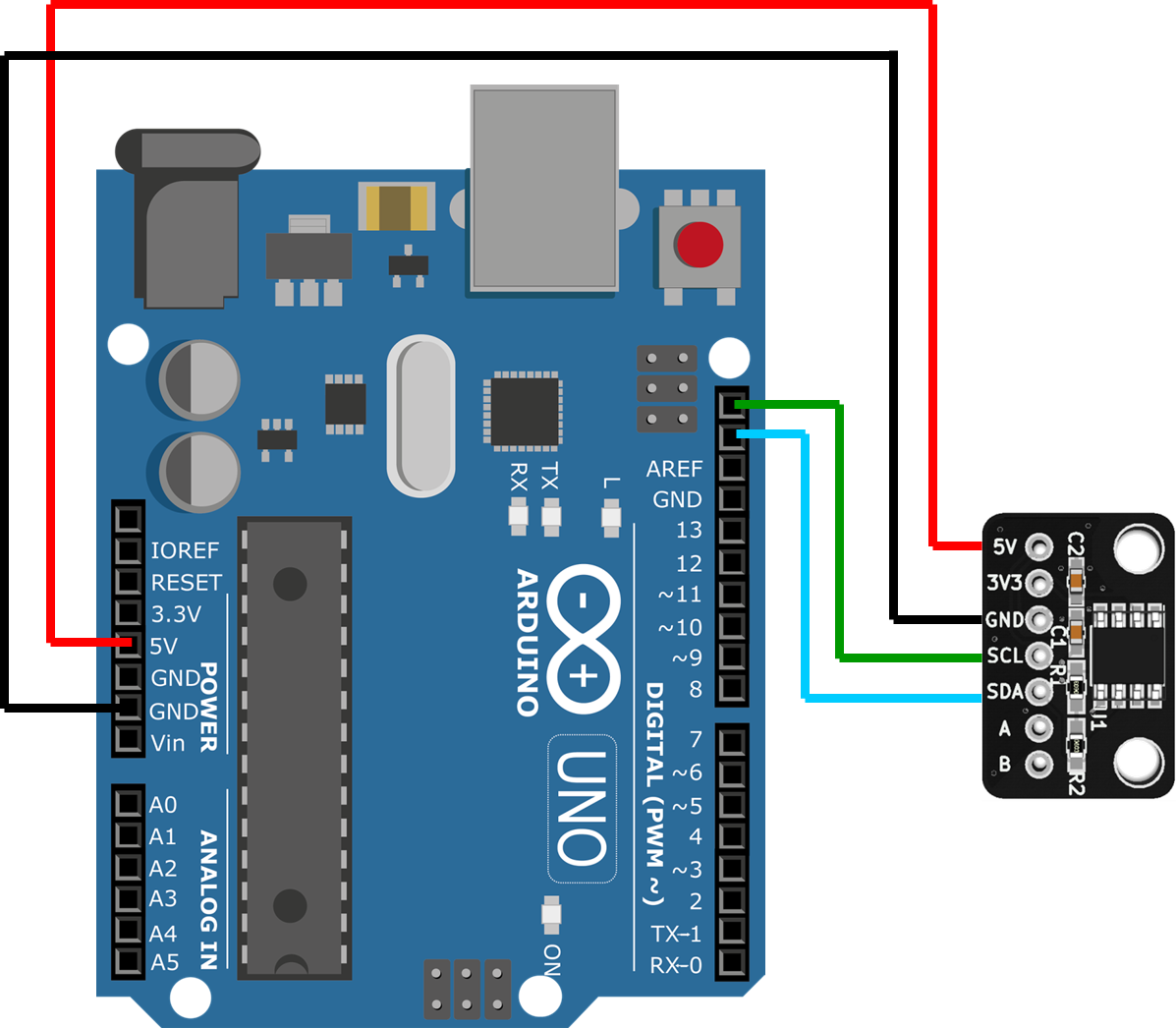
Source code
Minimum code
#include <stdint.h>
#include <Wire.h>
#define AS5600_AS5601_DEV_ADDRESS      0x36
#define AS5600_AS5601_REG_RAW_ANGLE    0x0C

void setup() {
  // I2C init
  Wire.begin();
  Wire.setClock(400000);

  // Read RAW_ANGLE value from encoder
  Wire.beginTransmission(AS5600_AS5601_DEV_ADDRESS);
  Wire.write(AS5600_AS5601_REG_RAW_ANGLE);
  Wire.endTransmission(false);
  Wire.requestFrom(AS5600_AS5601_DEV_ADDRESS, 2);
  uint16_t RawAngle = 0;
  RawAngle  = ((uint16_t)Wire.read() << 8) & 0x0F00;
  RawAngle |= (uint16_t)Wire.read();
  // Raw angle value (0 ~ 4095) is stored in RawAngle
}

void loop() {
}
Reading angles via incremental output pins
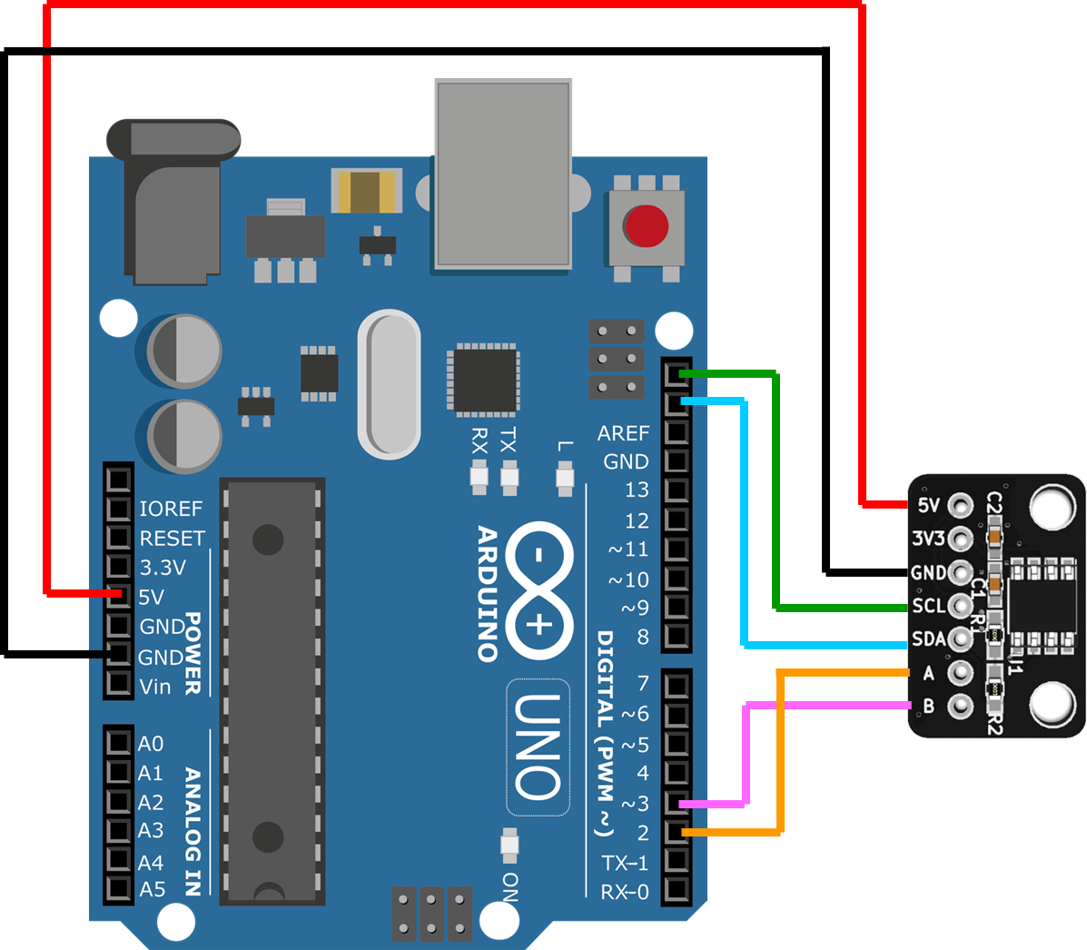
Source code
Minimum code
#include <stdint.h>
#include <Wire.h>
#define AS5600_AS5601_DEV_ADDRESS       0x36
#define AS5601_REG_ABN                  0x09

volatile int32_t EncoderCount;

void Encoder_GPIO_init(void) {
  DDRD  &= ~((1 << PD2) | (1 << PD3));  // Set PD2 and PD3 as input
  EICRA = 0b00000101; // Trigger event of INT0 and INT1 : Any Logic Change
  EIMSK = 0b00000011; // Enable interrupt INT0 and INT1
  sei();              //Enable Global Interrupt
}

// Encoder "A" pin logic change interrupt callback function
ISR(INT0_vect) {
  updateEncoderCount();
}

// Encoder "B" pin logic change interrupt callback function
ISR(INT1_vect) {
  updateEncoderCount();
}

void updateEncoderCount(void) {
  const static int8_t EncoderIndexTable[] =
    {0, -1, 1, 0,  1, 0, 0, -1,  -1, 0, 0, 1,  0, 1, -1, 0};
  static uint8_t EncoderPinState_Now, EncoderPinState_Prev = 0;

  EncoderPinState_Now = (PIND >> 2) & 0x03; // Bit1 : PD3 (Encoder B), Bit0 : PD2 (Encoder A)
  EncoderCount += EncoderIndexTable[EncoderPinState_Prev << 2 | EncoderPinState_Now];
  EncoderPinState_Prev = EncoderPinState_Now;
}

void Encoder_I2C_init(void) {
  // Set AS5601 resolution 2048ppr
  Wire.beginTransmission(AS5600_AS5601_DEV_ADDRESS);
  Wire.write(AS5601_REG_ABN);
  Wire.write(0b00001000);   // ABN(3:0)
  Wire.endTransmission();
  delay(1);
}

void setup() {
  // I2C init
  Wire.begin();
  Wire.setClock(400000);

  // Peripheral init
  Encoder_I2C_init();
  Encoder_GPIO_init();
}

void loop() {
  // Angle value (0 ~ 2047) is stored in EncoderCount
}
Fixing resolution by burning a config register
The default resolution of the AS5601 is 8 ppr, so you must set the resolution each time power is applied.
By setting the resolution to 2048 ppr and then burning the setting register with the Burn_Setting command, the resolution stays at 2048 ppr from startup even after power cycles, so you do not need to reapply the resolution or other settings via I2C.
Once the register is written, the resolution, filter settings, etc. cannot be changed.
Sample code is here.
Documents
Schematic
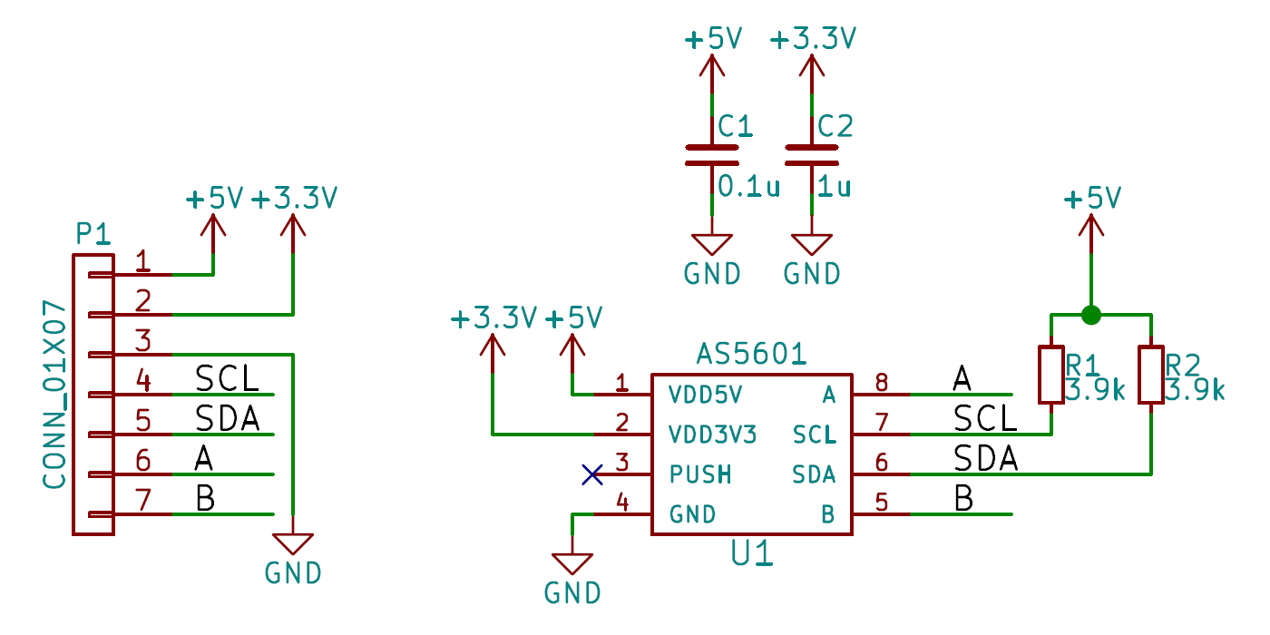
PDF file:schematic-v1_0.pdf
Dimensions
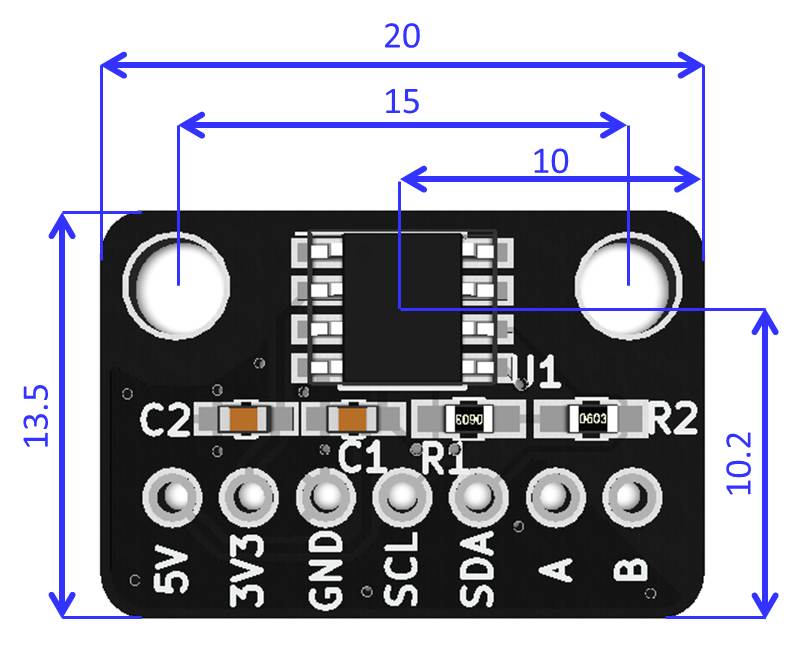
DXF file: dimension_dxf.zip
3D CAD Data
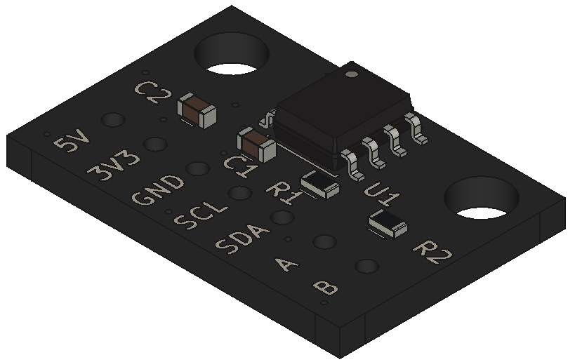
STEP file:3d_step.zip
