Japanese page
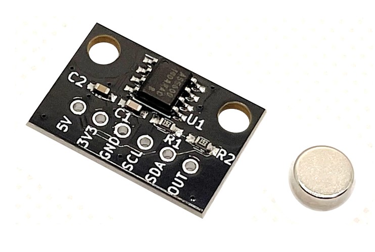
Breakout board for the AS5600 (ams AG) magnetic absolute rotary encoder with 12-bit (4096 ppr) resolution and 2.54 mm pitch.
A neodymium magnet is included.
Provides 5V/3.3V/GND power pins and I2C, analog, and PWM output pins. The supply voltage is 5V or 3.3V.
Features
- High resolution: 4096ppr
- Magnetic type enables non-contact angle measurement, excellent reliability and durability
- Interface
- I2C: Angle reading and operation setting are possible by accessing the config register
- Analog output: Analog voltage value corresponding to angle
- PWM: PWM signal with duty ratio corresponding to angle
- Sampling time: 150 us
- Can read values even when the AS5600 and magnet centers are offset by about 1 mm
Included Items
- Board ×1
- Neodymium magnet ×1
Specifications
- Board size: W20 x D13.5 mm
- Mounting holes: 15mm pitch, M3 x 2
- Magnet size: Φ6 x 2.5 mm
- Magnetization: Diametric
- When supplying 5V for power supply voltage, leave the 3.3V pin open. When supplying 3.3V, also supply 3.3V to the 5V pin.
- DIR pin is connected to GND. PGO pin is unconnected.
How to mount
- Attach the included magnet to the center of the rotor shaft.
- Attach the board to the fixture so that the center of the AS5600 aligns with the center of the magnet.
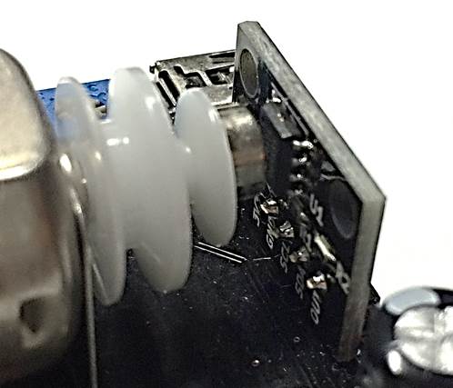
Example program with Arduino
Angle acquisition via I2C
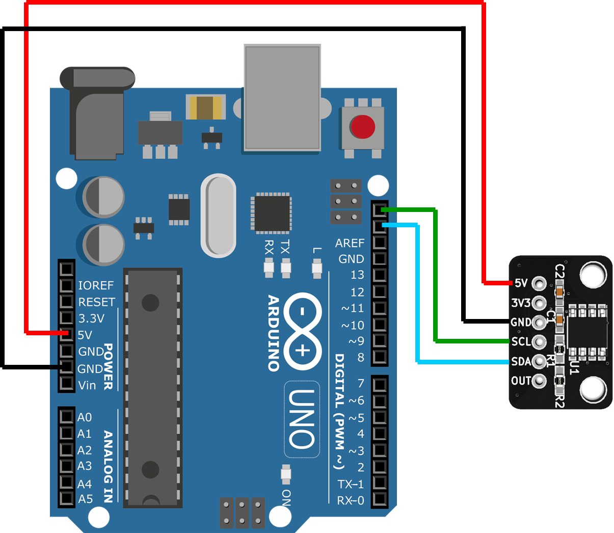
Source code
Minimum code
#include <Wire.h>
#define AS5600_AS5601_DEV_ADDRESS      0x36
#define AS5600_AS5601_REG_RAW_ANGLE    0x0C

void setup() {
  // I2C init
  Wire.begin();
  Wire.setClock(400000);

  // Read RAW_ANGLE value from encoder
  Wire.beginTransmission(AS5600_AS5601_DEV_ADDRESS);
  Wire.write(AS5600_AS5601_REG_RAW_ANGLE);
  Wire.endTransmission(false);
  Wire.requestFrom(AS5600_AS5601_DEV_ADDRESS, 2);
  uint16_t RawAngle = 0;
  RawAngle  = ((uint16_t)Wire.read() << 8) & 0x0F00;
  RawAngle |= (uint16_t)Wire.read();
  // Raw angle value (0 ~ 4095) is stored in RawAngle
}

void loop() {
}
Reading angles via analog output
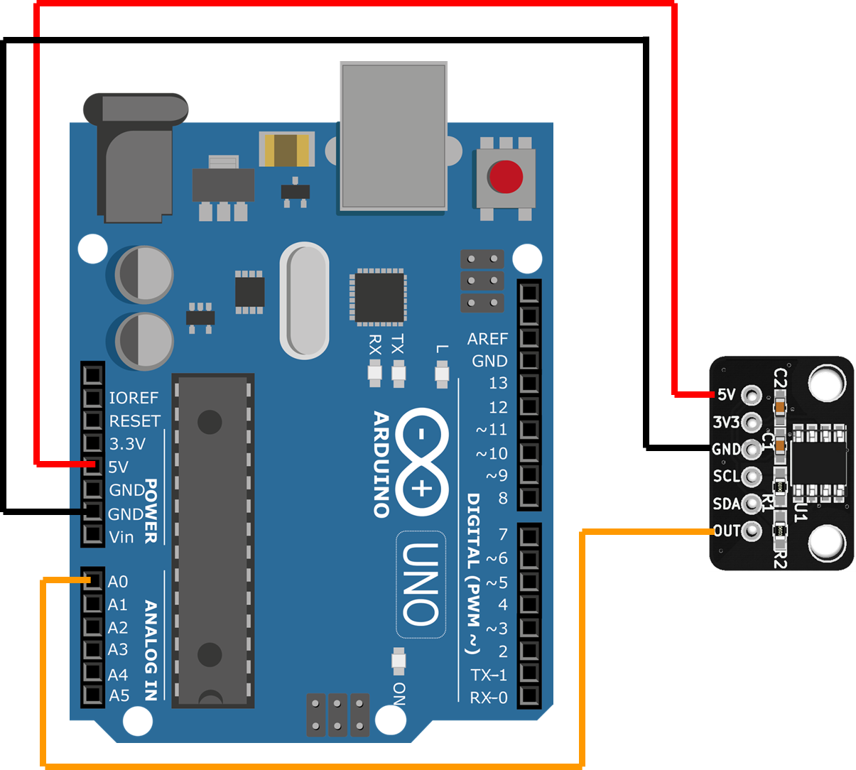
Source code
Minimum code
#include <stdint.h>

void setup() {
  uint16_t AnalogValue = 0;
  AnalogValue = analogRead(0);
  AnalogValue &= 0x03FF;
  AnalogValue = 0x03FF - AnalogValue;
  // Angle value (0 ~ 1023) is stored in AnalogValue
}

void loop() {
}
Documents
Schematics
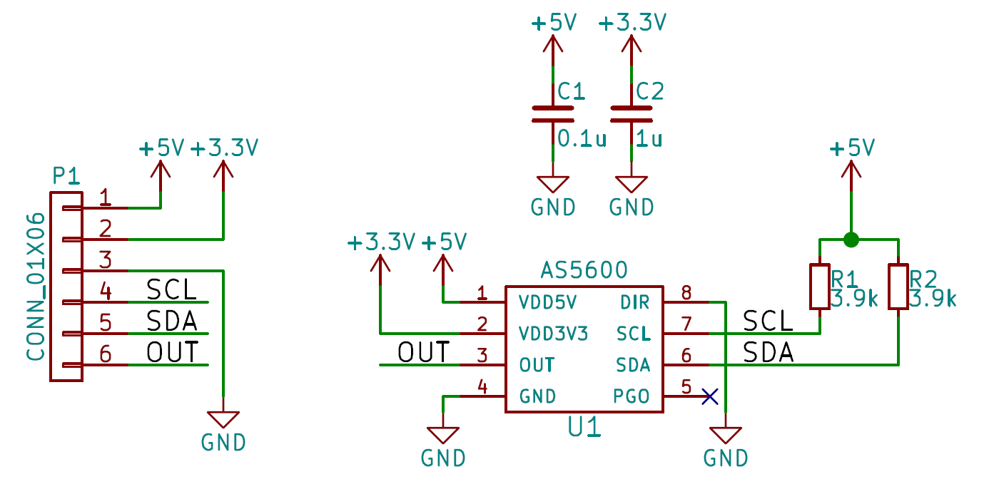
PDF file:schematic-v1_0.pdf
Dimensions
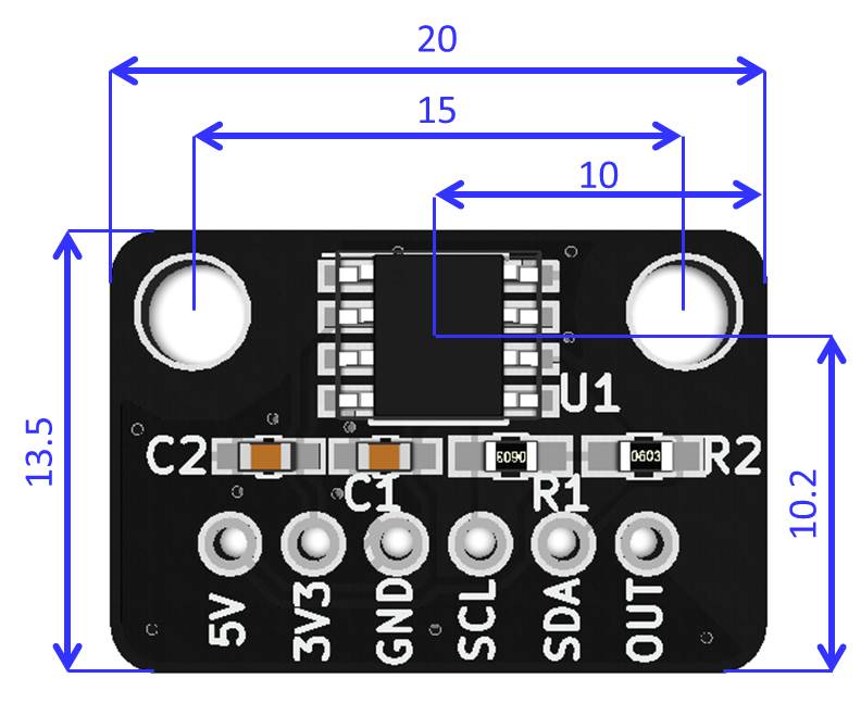
DXF file: dimension_dxf.zip
3D CAD Data
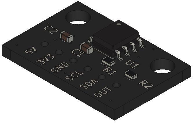
STEP file:3d_step.zip